TinyGS is a community-driven, open-source network of ground stations that receive data from small satellites, especially Low Earth Orbit (LEO) satellites, using low-cost hardware like LoRa (Long Range) radios and ESP32 microcontrollers. The name stands for Tiny Ground Station. Visit the website at TinyGS.
Architecture for Communication
This project implements a low-cost ground station for receiving data packets transmitted by CubeSats using LoRa communication operating in the 433MHz frequency band. The comprehensive system architecture is illustrated in Figure 1.1.
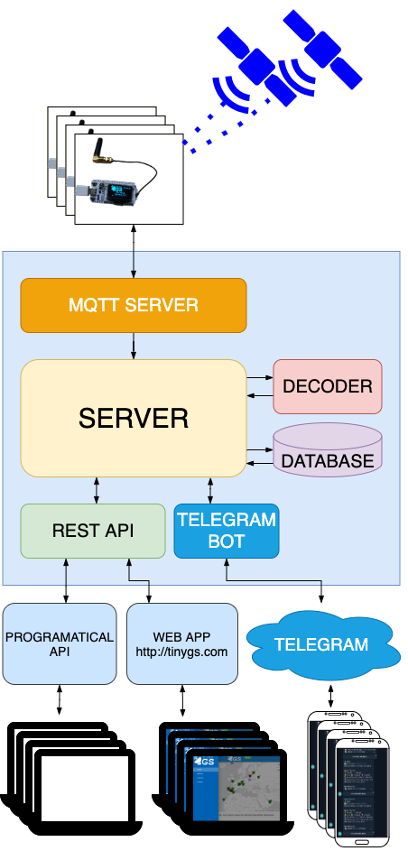
The communication process follows this sequence:
Satellite Transmission: CubeSats in Low Earth Orbit (LEO) broadcast data using LoRa protocol at 433MHz.
Ground Station Reception: Our custom ground station—comprising an SDR receiver, antenna, and computer running TinyGS software—captures these transmissions when satellites pass within range.
Data Processing: Received packets are published to an MQTT topic.
Data Distribution: The MQTT broker, subscribed to the relevant topic, forwards messages to the main server for decoding.
Client Access: Decoded data is served through a REST API, allowing various client applications (web interfaces, automated systems) to access and present the information.
The system can receive various types of satellite data, including telemetry information (location, power levels, temperature), and supports bidirectional communication, enabling ground stations to send commands to satellites for tasks like requesting specific imagery or adjusting orbital parameters.
Hardware Design
Our ground station design prioritizes cost-effectiveness and functional simplicity. The primary components include:
- ESP32 Microcontroller: Central processing unit
- OLED display: User interface for system status
- SX1278 LoRa module: RF communication component
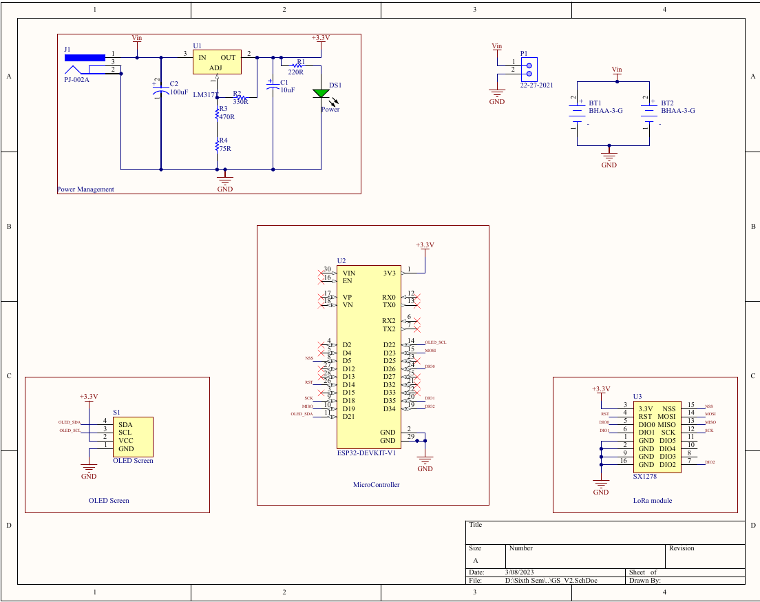
These components are integrated on a custom PCB designed for optimal data reception and MQTT server connectivity while maintaining low implementation costs. The schematic diagram of the main board is shown in Figure 1.2.
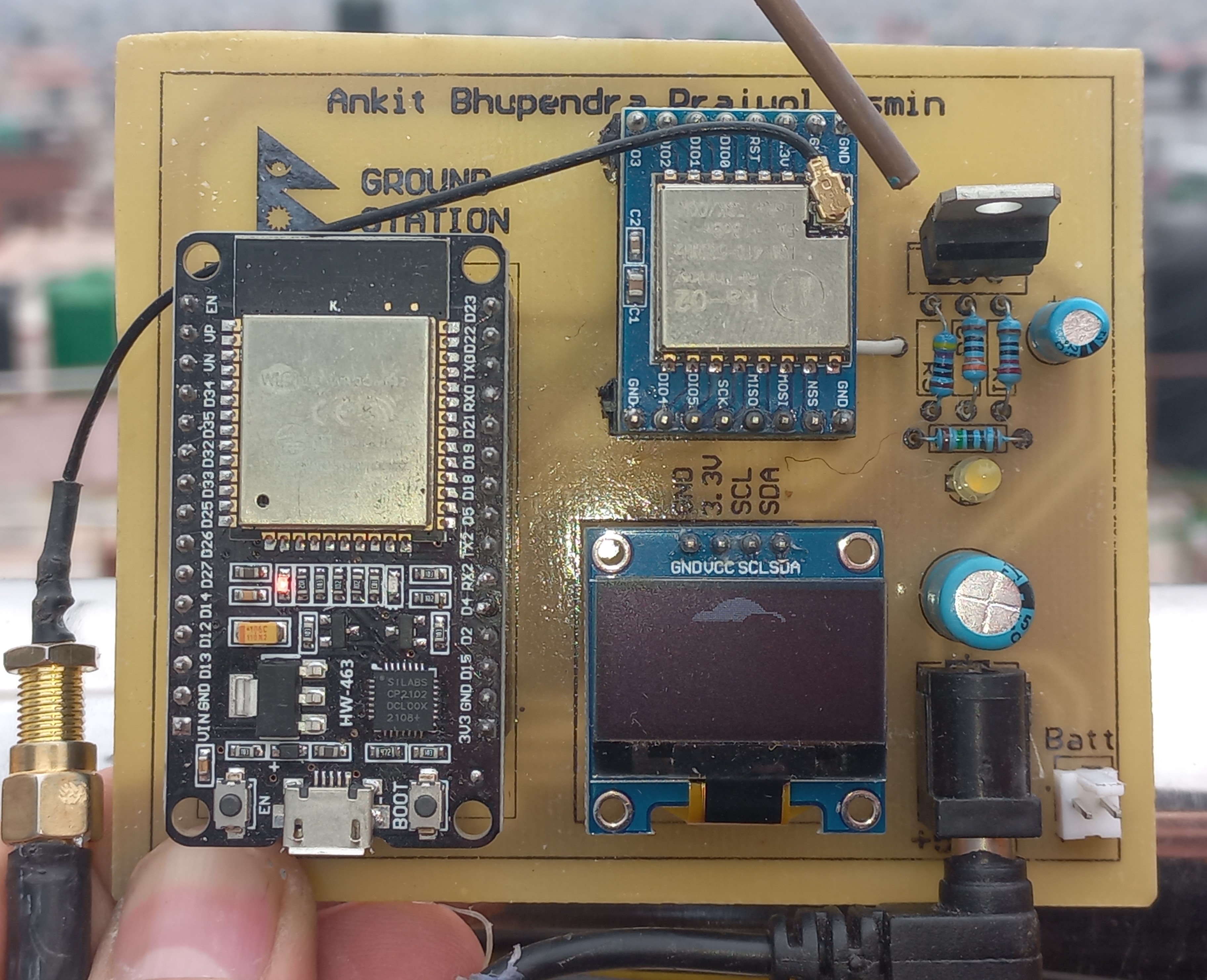
The completed hardware assembly after PCB fabrication and component soldering is shown in Figure 1.3.
Part 2: ANTENNA DESIGN
2.1 Theoretical Calculations
The antenna design focuses on creating a resonant structure for the 433MHz operating frequency. At resonance, an antenna exhibits purely resistive behavior, facilitating optimal impedance matching with the transmission line and maximizing radiated power.
The wavelength calculation for 433MHz follows:
$$ λ = c/f = 299,792,458 m/s ÷ 433,000,000 Hz = 0.692 m $$
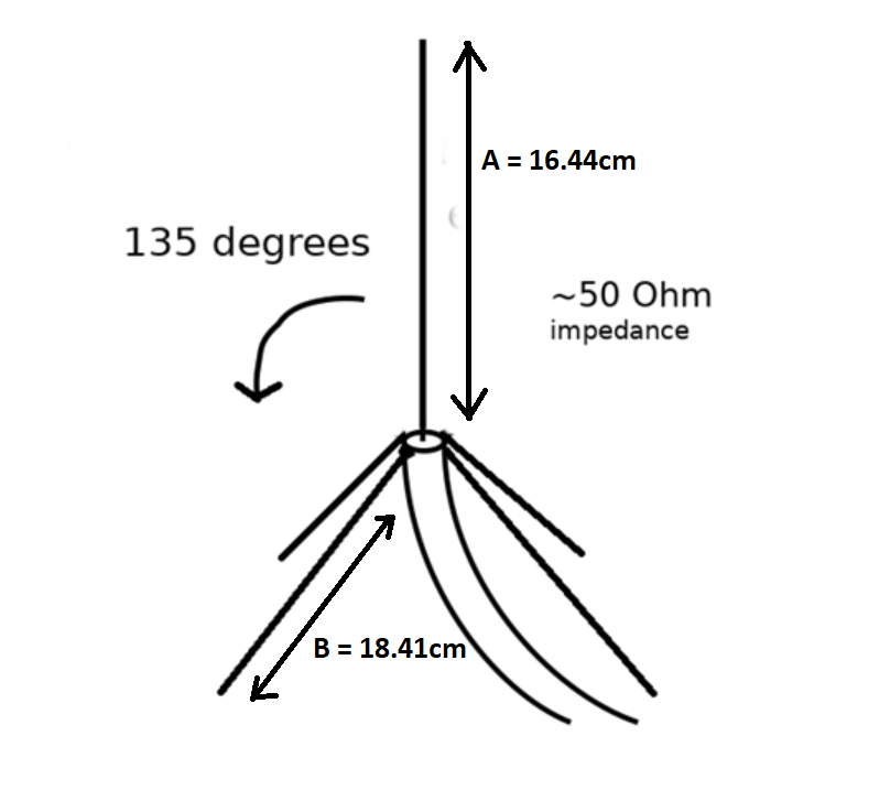
For our quarter-wave ground plane antenna, we calculate:
- Quarter wavelength: $λ/4 = 0.173 m = 17.3 cm$
- Adjusting for velocity factor (0.95): $17.3 × 0.95 = 16.44 cm$
- Radiating element length: $16.44 cm$
- Radial length: $(16.44 × 0.12) + 16.44 = 18.41 cm$
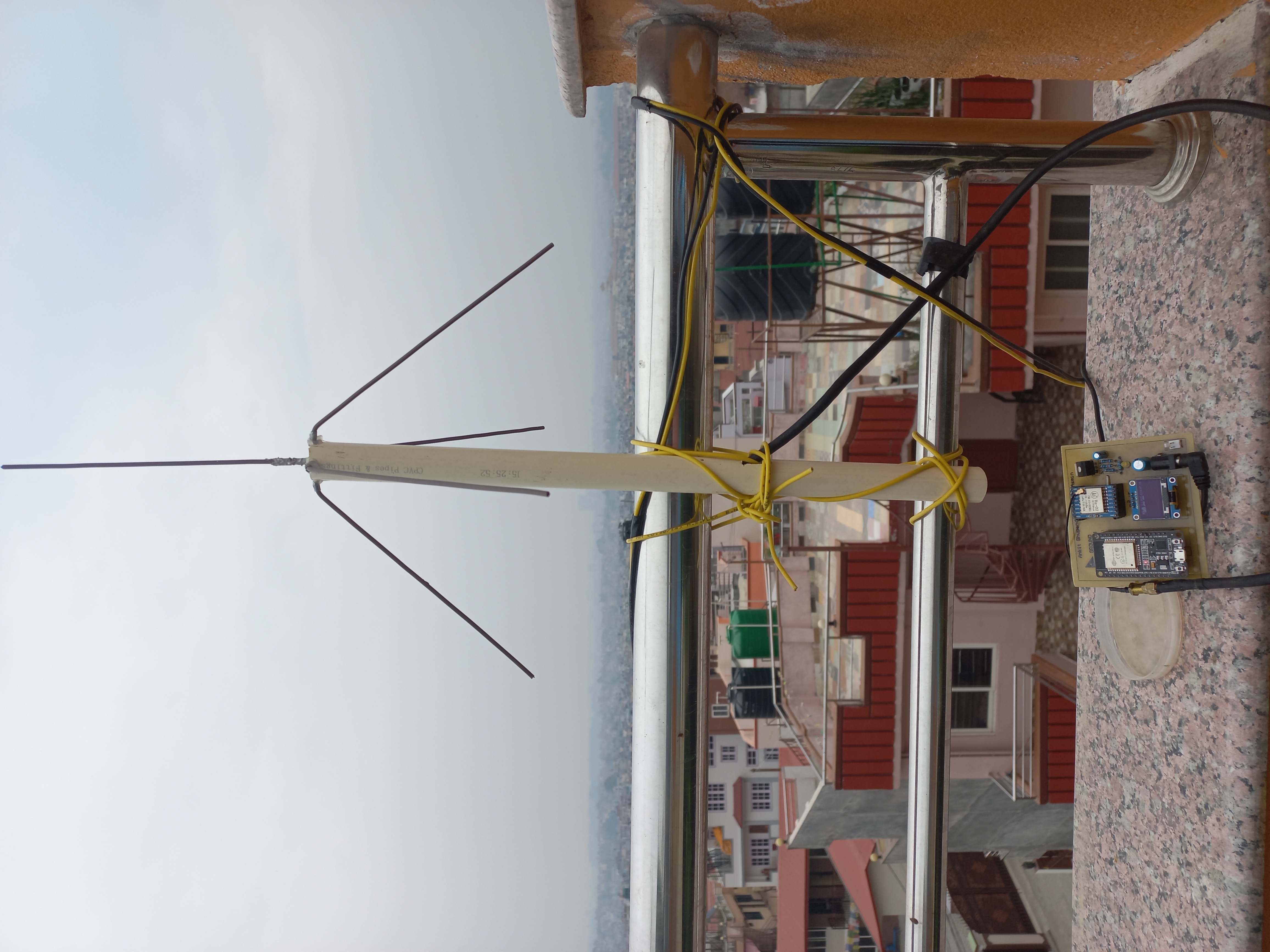
2.2 Construction and Impedance Matching
We constructed the antenna using:
- 12-gauge solid copper wire for both the radiating element and radials
- Standard SMA connector for RF interface
- The radiating element was soldered directly to the SMA connector’s central conductor
- Radials were attached to the connector’s ground plane using nuts and bolts
While a standard monopole with perpendicular radials (90° angle) has an impedance of approximately 37Ω, we adjusted the radials to form a 135° angle with the radiating element to achieve the required 50Ω impedance match to standard coaxial cable.
2.3 Antenna Selection Rationale
Our selection of a quarter-wave ground plane antenna over alternatives was based on several engineering considerations:
Impedance Matching: The need to match the 50Ω impedance of our coaxial feeder line.
Size Constraints:
- A half-wave dipole would require 34.6 cm total length
- Our quarter-wave design reduced this to 17.3 cm for the main element
Performance Characteristics:
- A simple monopole has reduced impedance (37Ω)
- The ground plane configuration creates a mirror effect that produces radiation patterns similar to a dipole
- Angling the radials at 135° raises the feedpoint impedance from 37Ω to the desired 50Ω
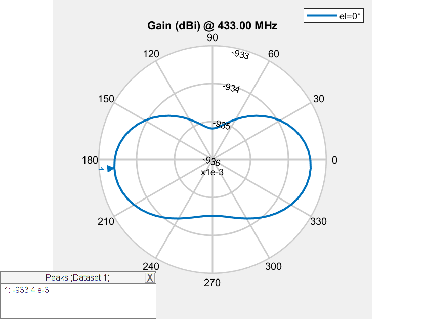
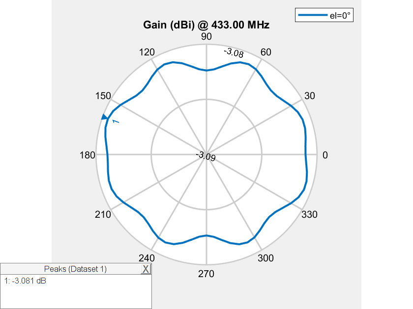
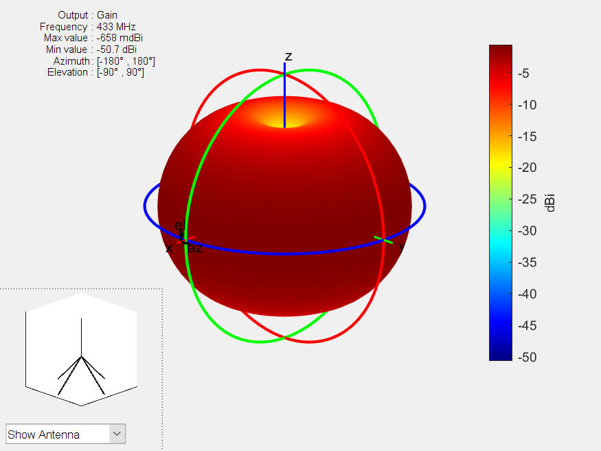
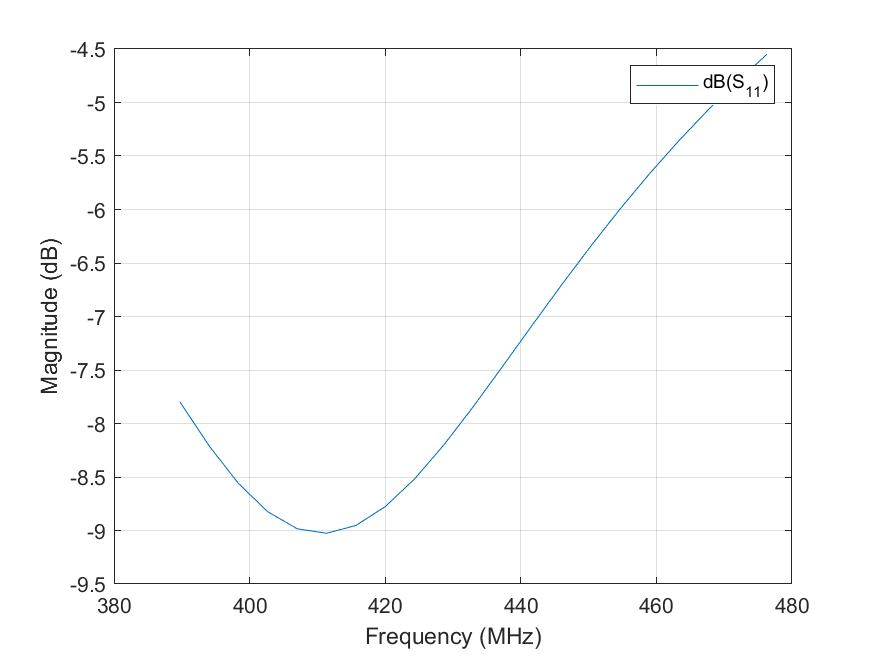
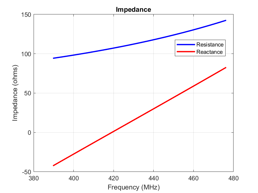
2.4 Radiation Pattern Comparison
The quarter-wave ground plane antenna provides superior performance for our application, as evidenced by the radiation pattern comparisons as shown in figures below.
Characteristics of Ground Plane antenna
Gain
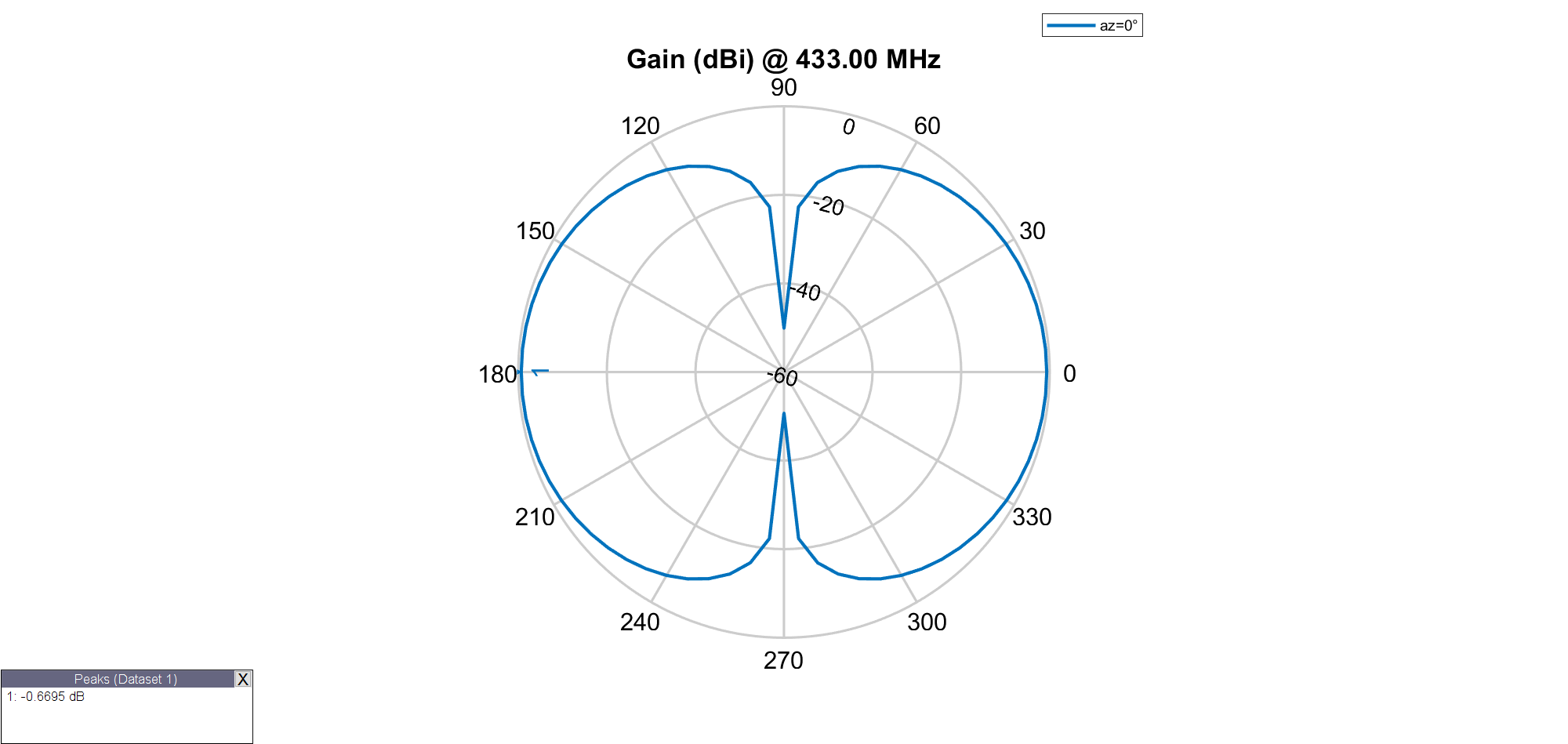
Radiation Pattern
Frequency-Magnitude Curve
Frequency-Impedance Graph
The ground plane configuration provides an optimal balance of size, impedance matching capability, and radiation efficiency for our satellite communication ground station.
Final Setup
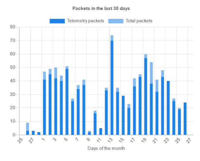
Telemetry Reception
Over the period of one month of leaving our antenna in open sky, we have received more than 400+ telemetry packets from more than 8 satellites.
The packets are received by a ground station, sent to the cloud MQTT broker using MQTT protocol, and decoded and stored in cloud server (which is also an MQTT client).
The raw packets in hexadecimal form (hexdump) look like this:
    0  1  2  3  4  5  6  7  8  9  A  B  C  D  E  F 0123456789ABCDEF
0000 EB FC 40 09 BE D2 1A 07 F8 18 61 B9 51 79 47 CE ..@.......a.QyG.
0010 CE CE D3 6E AC 8E 96 26 96 25 96 14 09 BE D2 19 ...n...&.%......
0020 00 00 4A D3 19 5E 3A AF 05 42 42 C2 F7 61 43 4D ..J..^:..BB..aCM
0030 A2 7B 41 F7 30 E9 43 02 B9 49 4A D3 19 5E 3A AF .{A.0.C..IJ..^:.
0040 05 42 42 C2 F7 61 43 4D A2 7B 41 F7 30 E9 43 02 .BB..aCM.{A.0.C.
0050 B9 49 00 00 00 00 00 00 00 00 00 00 00 00 00 00 .I..............
0060 00 00 00 00                                     ....
Then this hexdump is decoded in the server using decoder modules:
    {
  "header": {
    "netId": 235,
    "msgTypeId": 252,
    "headUnk": 64,
    "msgTypeId1n": 15,
    "msgTypeId2n": 12,
    "headUnk1n": 1
  },
  "payload": {
    "timestamp": 163500570,
    "satId": 7,
    "unk248xF8": 248,
    "unk24x18": 24,
    "unk81x51": 97,
    "unk121x79": 185,
    "unk81xx51": 81,
    "unk121xx79": 121,
    "unk71x47": 71,
    "unk206CEx3": [
      206,
      206,
      206
    ],
    "unkx211x110x172x142x150x38": [
      211,
      110,
      172,
      142,
      150,
      38
    ],
    "unkx150x37x150x20": [
      150,
      37,
      150,
      20
    ],
    "lastRXtime": 163500569,
    "unkx00x00": [
      0,
      0
    ],
    "unkValue": 6917295,
    "eccentricity": 0.001335300737991929,
    "inclination": 97.48316192626953,
    "ascending": 205.6346893310547,
    "angleX": 30.898881912231445,
    "angleY": 130.72377014160156,
    "unkValue2": 6917295,
    "eccentricity2": 0.001335300737991929,
    "inclination2": 97.48316192626953,
    "ascending2": 205.6346893310547,
    "angleX2": 30.898881912231445,
    "angleY2": 130.72377014160156,
    "tinygsTxPower": 3000,
    "satId1b": 0,
    "satId2n": 7
  },
  "telemetry": true,
  "tinygsSatellite": "2023-003A",
  "type": "Beacon"
}
This decoded information is parsed and displayed in TinyGS web application:
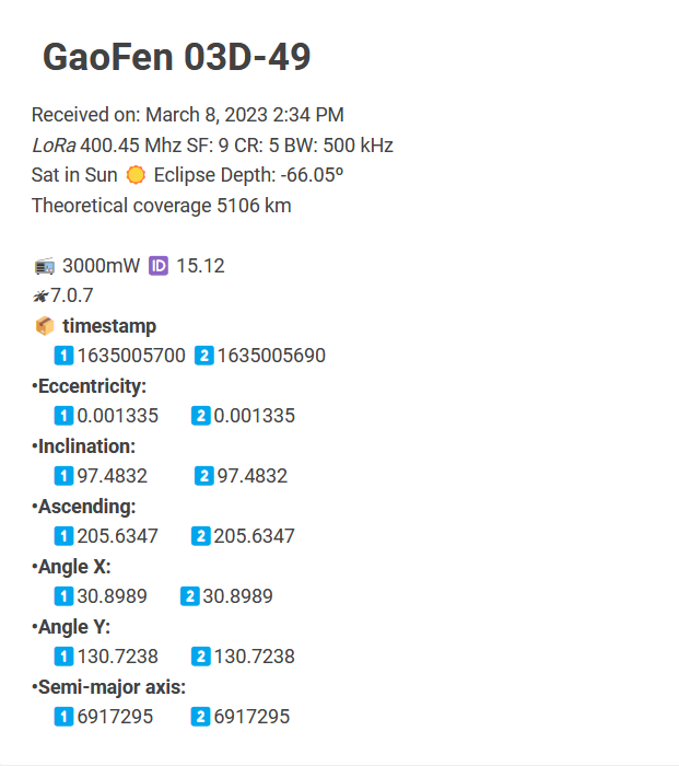
We successfully received the telemetry from numerous satellites.