Overview
This CAN board has a STM32G473CBT6 coupled with a CAN FD transceiver along with multiple connectors supporting I2C and SPI communication. The board was designed to facilitate CAN communication by four wire: CAN_H, CAN_L, GND, BUS Voltage. Bus Voltage can range from 12V-36V as the board has a built-in regulator which regulates required voltage to the microcontroller and peripherals.
For our final year college project. (Autonomous Vehicle) we wanted to have multiple independent nodes that could communicate to each other. We also wanted our system to be robust enough to combat failures if there were to appear any. There was need of differnet perepherials at different nodes. We searched our available market for boards that could fit our requirements but couldn’t find any. Thus, I decided to design it myself.
Part Selection
Quite tricky considering parts had to be imported and tax on such parts make it expensive.
Microcontroller Choice
I wanted a cheap microcontroller that could support CAN FD. After much market analysis and price comparison, I decided to go with STM32G4 series chip. It has:
- Three CAN-FD bus
- Plenty of peripheral support
- One limitation: only 128kb of EPROM
Board Design
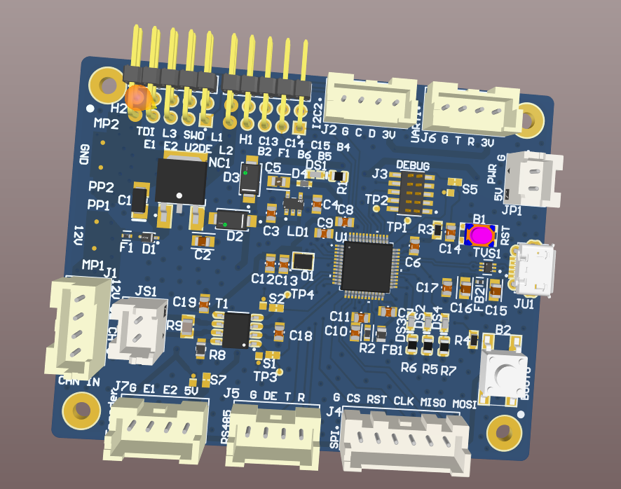
I started to design the board in Altium Designer, thanks to its educational license it was free to use and evaluate. Above is a 3D rendered model of our board in Altium Designer.
Design Principles
- Add multiple Solder Bridge for flexiblity in reconfiguration after board assembly. (This step was taken during Schematic Design)
- Follow the Datasheet for Designing Voltage Regulator and Filters
- Using TVS diode to protect from ESD.
- Test points in critical signal and power route.
- Debug Point (SWD)
PCB Stack UP
- L1 (Top): critical signals, MCU, transceiver
- L2 (GND): Solid ground plane
- L3 (PWR): 12 V, 5 V and 3V3 planes
- L4 (Bottom): Signals (Mostly Slow: I/O, connectors)
- Impedance targets: 120 Ω differential for CANH/CANL;
Design Challenges
As I went along with the design guidelines provided by ST for STM32G4 series boards, one particular difficulty was in oscillator choice. I chose a bypass oscillator rather than a crystal. The main difference is:
- Oscillator: Produces the clock signal by itself (active device) and the microcontroller is able to read that signal through a single pin
- Crystal: Passive components, need matching capacitors and resonate to their fundamental frequency. Two pins are needed to probe the input and output of the oscillator circuit and provide necessary feedback to maintain oscillation
Manufacturing and Assembly
After completing the design in Altium, I ordered:
- Parts through Digikey
- PCB through JLCPCB
The boards were of good quality and with the parts arrived I started to work on assembling the board. I did not have a heat plate so I had to get creative here. I cut the excess stencil and put the board on top. Concentrated heat is not good for any PCB. I put the PCB on top of the stencil and heated the stencil warming up the board then heating the components from top which is illustrated in the video.
Testing and Software Development
Initial Testing
After the assembly, I wrote a quick code to test the built-in LED of the chip, which was a success.
CAN Communication
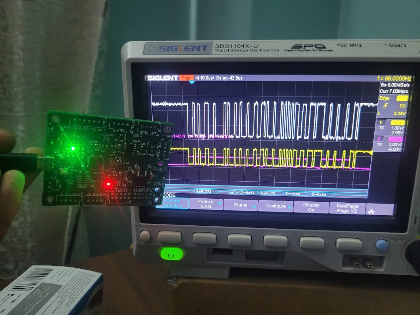
Later I wrote a simple CAN program to transmit data which was viewed in an oscilloscope.
Zephyr RTOS Integration
I started to port Zephyr RTOS to this custom board and could run all the example programs.
Repository: GitHub - silwalasmin/CANBoard
Conclusion
This project was a big success and helped us to build our final year college project.